| |
|
| So far we have not talked
about the TUBING and FITTINGS that connect our various LC
modules together. For tubing connections between the
reservoir and the pump and the injector, the only
requirement is that the fittings not leak, and that the
tubing between the reservoir and the pump be large enough
in diameter so that flow of mobile phase to the pump is
not restricted. The tubing connections between the
injector and the column, and from the column to the
detector, however, require more attention.
|

Connections between the
reservoir and the pump are usually made with Teflon
tubing, often of fairly wide bore. Connections downstream
of the pump are usually made with stainless steel or PEEK
(poly ether ether ketone) tubing. Connections between
injector-column and column-detector should be made from
narrow-bore tubing (0.010" i.d. or less) in order to
minimize dead volume.
|
| |
|
| This part of
the LC system must be carefully designed and constructed
in order to minimize the volume of both the fittings and
tubing. We say that we have to eliminate dead volume
as much as possible. So we need to keep the tubing
length short, and we will usually use tubing of very
narrow diameter: 0.010 inch internal diameter (or "ten
thousandths") is the usual tubing size for this part
of the system (smaller tubing may be required for use
with "microbore" columns; larger tubing should
only be used with preparative columns). If for any reason
we have to replace the tubing or connections in this part
of the LC system (between the injector and detector), BE
VERY CAREFUL TO SELECT THE RIGHT TUBING SIZE AND THE
RIGHT FITTINGS.
|
|
| Let's
talk next about the fittings used in LC. These are called
compression fittings and their design is illustrated
below. A piece of
tubing is first equipped with a NUT and FERRULE as shown
at the right. To connect this end of the tubing with
another fitting (the column end, a tee, connector, etc.)
for the first time, just screw the nut into the fitting. Be
careful not to overtighten the fitting! Usually
the nut should be tightened finger-tight and then an
additional 3/4 of a turn (270 degrees clockwise) with a
wrench.
When reassembling an
existing fitting (when changing columns, for example),
the nut should be tightened finger-tight and then snugged
slightly with a wrench to prevent leaks.
|
Standard compression
fitting used in HPLC.
|
| |
|
| Unfortunately, not all
fittings are interchangeable. This is a major headache
for most LC workers, but we have to live with it for the
time being. Usually mismatched fittings appear to work,
and this makes the situation even worse. That is, the
fittings will appear to go together in the usual way.
However mismatched fittings will not work properly. The
reason is that the main difference in these fittings is
the distance between the tubing end and the ferrule, as
shown at the right.
|
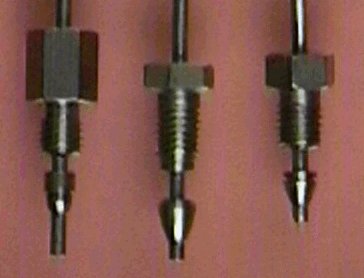
Note the difference in
the distance from the bottom of the ferrule to the end of
the tube in these three tube ends assembled with fittings
from different manufacturers.
|
| |
|
| If this
distance is too long for the body of the fitting, the
ferrule will not seat properly, and the fitting will leak.
If the distance is too short, the ferrule will seat, no
leak will occur, but a "dead volume" will be
created. This is most insidious, because then our
separation will not be as good as it should be, but
everything else will look OK. Dead volumes are like the
cancer of HPLC - hidden, but a real "killer".
Dead volume between the injector and the column permits
dilution of the initial sample with mobile phase, causing
band broadening. Dead volume between the column and the
detector cell undoes the separation already accomplished
on the column by allowing re-mixing of separated
components.
|
|
| The fittings for the ends
of the column are similar to tubing fittings. A ferrule
and nut on the column hold the column into the end
fitting - just like tubing is connected together. Because
the column is packed with small particles of column
packing, it is necessary to have a way to hold these
particles in the column. This is usually achieved with a
FRIT - a small, coin-shaped piece of sintered metal
having narrow pores. Most column frits are nominally 2-micron
porosity, although smaller frits (0.5 micron) are used
for columns of very small particles (3-micron diameter).
|
|
| |
|
| If we
disconnect the column end-fitting, we can see the frit on
the top of the column. This frit can be removed and
replaced with a new frit if the old frit becomes plugged.
However if we do this, WE HAVE TO BE VERY CAREFUL. If the
column packing at the inlet is disturbed, it could ruin
the column permanently.
|
|
| |
|